

Your electronic product works perfectly on the workbench. But will it still perform reliably when surrounded by other electronic equipment?
A switching power supply can introduce unwanted noise into a signal. A fast digital clock can radiate interference through an unshielded cable. Even an electrostatic discharge that appears harmless can reset a controller or disrupt an entire system.
These are not simply engineering inconveniences. They are real electromagnetic compatibility (EMC) challenges that can affect product performance, reliability, and readiness for the European market.
The EMC Directive 2014/30/EU establishes requirements intended to ensure that electrical and electronic equipment operates without creating unacceptable electromagnetic interference and remains sufficiently resistant to electromagnetic disturbances.
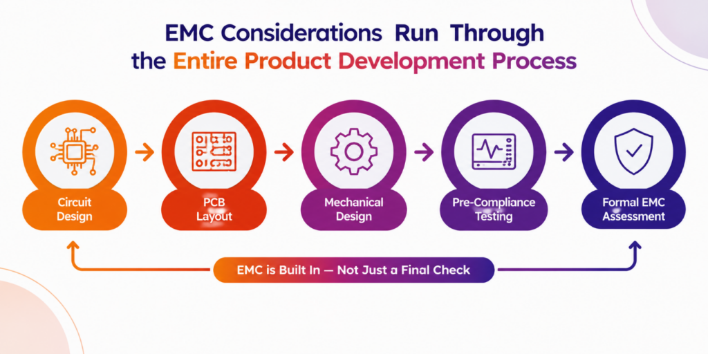
For manufacturers planning to place products on the European Union market, EMC compliance should not be treated as a final laboratory exercise. It influences decisions throughout product development, including:
The earlier EMC considerations enter the design process, the easier it becomes to identify potential issues while corrective changes are still manageable.

The EMC Directive 2014/30/EU provides the legal framework for assessing electromagnetic compatibility and demonstrating conformity before applicable equipment is placed on the EU market.
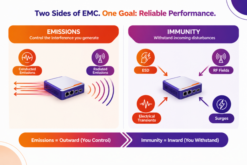
In practical terms, a compliant product must address two fundamental requirements:
Both requirements matter.
A device that produces very little interference but resets when someone touches its enclosure may have an immunity problem. Conversely, a device that operates reliably on its own but disrupts nearby equipment may have an emissions problem.
EMC compliance therefore requires evaluating the complete product—not merely confirming that its circuit functions correctly under ordinary operating conditions.
The applicable requirements, test methods, and performance criteria depend on the product, its intended environment, and the relevant standards.
The directive applies broadly to electrical and electronic apparatus and fixed installations, subject to its scope and specific exclusions.
For manufacturers, the central question is whether equipment can generate electromagnetic disturbances or be affected by them in ways that matter to its intended operation.
Two essential areas require consideration: electromagnetic emissions and electromagnetic immunity.
3.1 Electromagnetic Emissions
Every electronic circuit produces some level of electromagnetic energy. EMC emissions testing evaluates whether unwanted emissions remain within the applicable limits.
Emissions generally fall into two categories.
Conducted emissions
Conducted interference travels along conductive paths, including power supplies, mains connections, and signal interfaces.
Common sources include:
Radiated emissions
Radiated interference propagates through the air. PCB traces, enclosure openings, connectors, and attached cables can unintentionally act as antennas.
Controlling emissions requires more than selecting low-noise components. Grounding, return-current paths, filtering, shielding, and cable interfaces all influence the final result.
“A low-noise component does not guarantee a low-emission product. The complete design determines how electromagnetic energy is generated, coupled, and radiated.”
3.2 Electromagnetic Immunity
Electromagnetic immunity describes a product’s ability to maintain acceptable operation when exposed to external electromagnetic disturbances.
Depending on the product and applicable standards, immunity testing may include:
Test type | What it evaluates |
Electrostatic discharge (ESD) | Response to discharges caused by people or objects touching equipment or approaching accessible surfaces |
Radiated RF immunity | Performance in electromagnetic radio-frequency fields |
Electrical fast transient/burst | Response to repetitive, fast electrical disturbances associated with switching and inductive loads |
Surge immunity | Resilience to higher-energy transient overvoltages |
Conducted RF immunity | Susceptibility to RF disturbances coupled onto cables |
Voltage dips and interruptions | Behaviour during temporary reductions or interruptions in supply voltage |
A product does not necessarily have to operate without any change during every disturbance. Its required behaviour depends on the applicable product standard and defined performance criteria.
These criteria should be established before testing begins so that results can be assessed consistently.
If you are developing electronic equipment for the European market, assessing the EMC Directive should be an early part of your regulatory planning.
However, the applicable conformity route depends on the product’s function, configuration, and intended use.
4.1 Products Requiring EMC Consideration
Examples of products that generally require EMC consideration include:
The final classification depends on the product and its intended use. Some equipment may also be subject to other EU legislation that incorporates or takes precedence over particular EMC requirements.
4.2 What About Radio Equipment?
Equipment within the scope of the Radio Equipment Directive (RED) 2014/53/EU follows the RED conformity route, which incorporates essential electromagnetic compatibility requirements for radio equipment.
A product containing wireless connectivity should therefore be assessed carefully rather than automatically treated as an ordinary EMC Directive product.
Other regulatory requirements may also apply, depending on the product’s design and function.
4.3 Are Electronic Components Exempt?
Not necessarily.
Components and subassemblies intended for incorporation into other equipment, which cannot perform a direct function for the end user, may fall outside the EMC Directive’s definition of apparatus.
However, this is not a blanket exemption for every module or PCB. A module marketed as a finished product with a direct function may require its own conformity assessment.
The same care applies to claimed exclusions for inherently benign equipment, custom-built professional evaluation kits, and other categories. Each exclusion has specific conditions.
The practical step: Establish the product’s regulatory classification before committing to a test plan or making compliance claims.
For EMC alone, the directive generally allows manufacturers to demonstrate conformity through an internal production-control procedure. A notified body is not normally required for this route, and the manufacturer remains responsible for demonstrating that the equipment meets the applicable essential requirements.
A structured compliance process helps engineering teams identify the relevant requirements, prepare representative test configurations, investigate failures, and maintain supporting documentation.
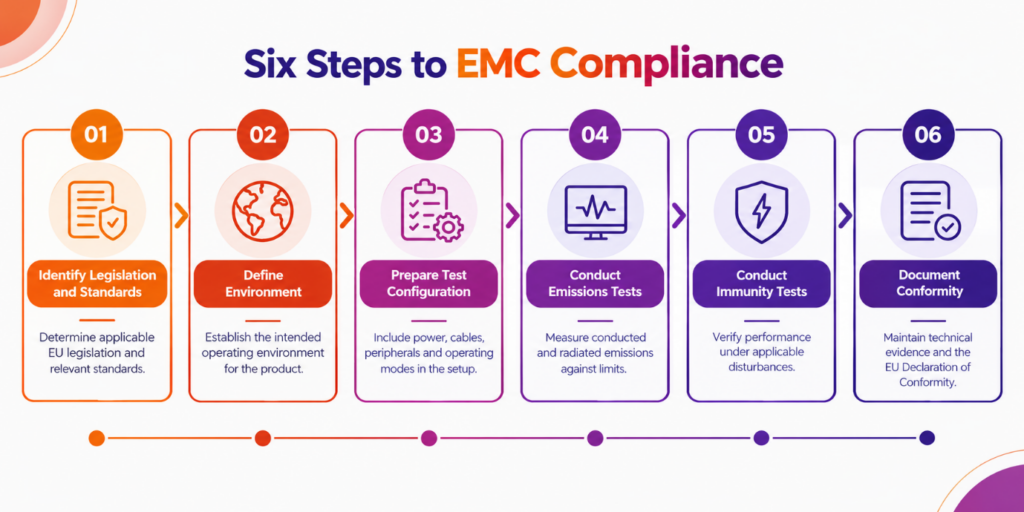
Step 1: Identify Applicable Legislation and Standards
Start by determining which EU legislation applies to the complete product.
Next, identify the relevant harmonised European standards. When their references are published in the Official Journal of the European Union and they are applicable to the product, these standards provide recognised methods for demonstrating conformity with the essential requirements.
Product-specific or product-family standards should be considered first where available. Generic standards are commonly used when no more specific standard applies.
Examples of generic EMC standards include:
The appropriate standard and edition must be verified for the product, its intended environment, and the current harmonisation status.
Step 2: Define the Intended Operating Environment
The intended environment influences the applicable limits and immunity requirements.
Residential, commercial, light-industrial, and industrial environments can have different electromagnetic conditions and standard requirements.
For example, industrial equipment may be designed for environments with more severe disturbances, while residential equipment can face stricter emissions limits in relevant frequency ranges.
This distinction should be established before testing—not after a product fails.
Step 3: Prepare the Complete Test Configuration
An EMC test should represent the product as it is intended to be used.
Preparation may include documenting:
Testing a bare PCB can provide useful engineering information. However, it does not establish compliance of the finished product when the enclosure, cables, and firmware materially affect its electromagnetic behaviour.
Step 4: Perform Emissions Testing
Conducted and radiated emissions measurements help identify unwanted electromagnetic energy and determine whether it meets the applicable limits.
Conducted emissions measurements commonly examine the 150 kHz to 30 MHz range on applicable power ports. Radiated emissions testing commonly starts at 30 MHz and may extend to higher frequencies, depending on the applicable standard and equipment characteristics.
The exact ports, frequency ranges, limits, detectors, and test arrangements depend on the applicable requirements.
The objective is to identify unwanted emissions, compare the results against relevant limits, and determine whether corrective action is necessary.
Step 5: Perform Immunity Testing
During immunity testing, the laboratory exposes the equipment to applicable electromagnetic disturbances while monitoring its behaviour.
Before testing, the manufacturer should define acceptance criteria for each relevant operating mode. These may address:
Clear acceptance criteria make results more meaningful and reduce ambiguity when evaluating failures.
Step 6: Document Conformity
Technical documentation should provide evidence supporting the conformity assessment.
Depending on the product, this may include:
The manufacturer must also satisfy applicable CE marking and other legal obligations.
EMC failures are often symptoms of design decisions made much earlier in the development cycle.
Understanding common failure mechanisms helps engineering teams identify risks before they lead to expensive redesigns.
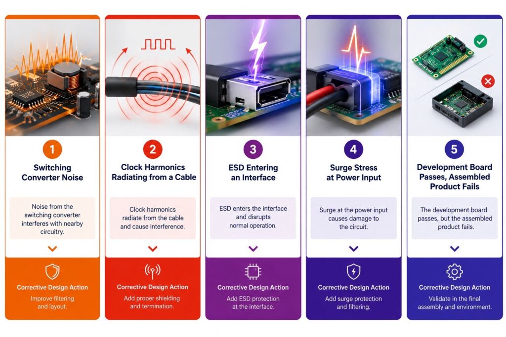
6.1 Switching Converters Create Excessive Emissions
Switching power supplies contain fast voltage and current transitions that can generate broadband noise and harmonics.
Poorly controlled current loops, inadequate filtering, and high-impedance return paths can allow this noise to spread through the PCB or escape through external cables.
How to reduce the risk:
6.2 Clock Harmonics Appear Across the Emissions Sweep
High-speed digital signals contain frequency components beyond their fundamental clock frequencies. Fast edge rates can produce significant energy at higher harmonics.
When these signals couple into connectors or long cables, the cables can radiate unwanted energy.
How to reduce the risk:
6.3 ESD Causes Resets or Unexpected Behaviour
Electrostatic discharge can enter through accessible surfaces, connector shells, buttons, and other exposed interfaces.
Poorly managed discharge currents may couple into sensitive circuitry and disrupt system operation.
A common mistake is to assume that connecting the enclosure and PCB ground at a single arbitrary point will always provide adequate protection.
The correct arrangement depends on the enclosure, discharge path, circuit architecture, and protective components.
How to reduce the risk:
6.4 Surge Testing Exposes Weak Input Protection
Mains-powered equipment may fail surge testing when its input protection strategy does not adequately coordinate protective components, insulation design, and grounding.
A protection component selected in isolation is not a complete protection strategy.
How to reduce the risk:
6.5 The Product Passes on the Bench but Fails in the Laboratory
A development board may perform well until it is installed in its final enclosure, connected to production cables, or operated with its full firmware.
Changes to the enclosure can alter shielding and resonances. Cable routing can create new radiating structures. Firmware can activate operating modes that produce different emissions.
How to reduce the risk:
Perform pre-compliance checks throughout development and test a representative production configuration before formal assessment.
The most effective EMC strategy begins during architecture and PCB design.
Rather than treating compliance as a final approval step, integrate electromagnetic considerations into every development phase.
Development stage | Key EMC considerations |
Circuit design | Identify noisy switching nodes, sensitive analogue circuits, high-speed interfaces, and external connections. |
PCB layout | Control return-current paths, minimise loop areas, separate noisy and sensitive circuitry where appropriate, and maintain reference-plane continuity. |
Mechanical design | Consider shielding effectiveness, enclosure seams, apertures, connector bonding, and interactions between conductive parts. |
Firmware development | Define representative operating modes and ensure predictable behaviour during immunity testing. |
Verification | Use pre-compliance measurements to identify problems, investigate coupling mechanisms, and validate corrective actions before formal testing. |
This approach helps teams discover problems while design changes are still manageable.
Pre-compliance testing is particularly useful for identifying potential emissions and immunity issues before formal laboratory assessment. It supports investigation and corrective action without replacing the need to demonstrate conformity using the applicable requirements.
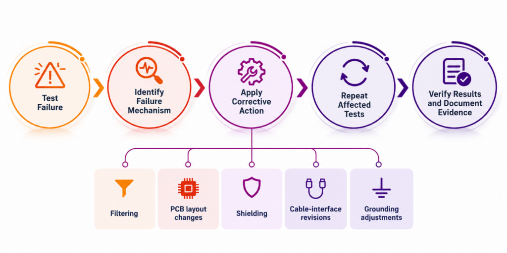
An EMC test failure does not automatically mean that a product can never be placed on the market. It means the relevant conformity requirements have not yet been demonstrated.
The next step is to understand the failure mechanism.
Depending on the findings, an engineering team may need to:
Some issues may be resolved with relatively small modifications. Others may require substantial redesign.
After corrective action, the affected tests should be repeated as appropriate to verify the solution and establish a reliable compliance record.
The Impact Goes Beyond Laboratory Fees
The financial implications of a failed EMC test are not limited to the cost of additional testing. Delays can affect:
This is why early assessment and pre-compliance testing are valuable. They help identify risks while design changes are still relatively inexpensive.
The EMC Directive 2014/30/EU is a fundamental consideration for many electronic products entering the European market.
Its requirements cover both emissions and immunity. Demonstrating conformity involves more than confirming that a circuit functions correctly in isolation. The complete product must be evaluated in the context of its intended environment, interfaces, and operating conditions.
For manufacturers, the most practical route is a structured process:
The earlier EMC enters the design process, the fewer surprises are likely to appear in the test chamber.
Treating EMC as an integral engineering responsibility helps teams identify risks earlier, investigate failures more effectively, and work towards product readiness with greater confidence.
sure which directives and standards apply to your product?
Start with the Compliance Route Finder to identify the likely regulatory requirements for your equipment.
From there, an assessment call can help translate those requirements into a practical test plan, including the recommended sequence, technical priorities, and budget.
A clear compliance route gives your engineering team something valuable: the confidence to move from prototype to market with fewer surprises.
Regulatory note: This article is intended as general technical guidance, not a substitute for a product-specific conformity assessment. Verify the current consolidated legislation, applicable harmonised standards, and their references in the Official Journal of the European Union before making conformity claims.

Dr. Ananth Krishna is the Vice President of Millennium TestLabs Pvt. Ltd. Over his 26+ years of Product Assurance career with MNCs such as Honeywell International, Tech Mahindra, Robert Bosch, General Motors and VXLeTech has led series of bold transformation and delivered proven business results in the area of EMC/EMI and product engineering. Being an Auditor for NABCB, NABL, A2LA, and NVLAP.<br>
His Doctorate and Patents (count more than 2 dozen with individual and shared) gives the right blend of technology understanding that creates cutting-edge home-grown technology in the niche EMI/EMC area.
The EMC Directive 2014/30/EU establishes requirements for electromagnetic compatibility of applicable electrical and electronic equipment placed on the EU market. It addresses both electromagnetic emissions and immunity, helping ensure products do not create unacceptable interference and can operate reliably in their intended electromagnetic environment.
Many electrical and electronic products, including industrial control units, power supplies, electronic instruments, automation equipment, and appliances with electronic control circuits, require EMC consideration. The applicable requirements depend on the product's function, intended use, and regulatory classification. Radio equipment may follow the Radio Equipment Directive (RED) 2014/53/EU instead.
EMC emissions testing measures unwanted electromagnetic energy generated by a product to determine whether it meets applicable limits. Immunity testing evaluates how the product performs when exposed to external disturbances, such as electrostatic discharge (ESD), radiated RF fields, electrical fast transients, and surges.
Manufacturers should consider EMC from the early design stages, including circuit architecture, PCB layout, grounding, enclosure design, and cable routing. Pre-compliance testing can help identify potential emissions and immunity issues before formal laboratory assessment, reducing the risk of costly redesigns and project delays.
An EMC test failure means the applicable conformity requirements have not yet been demonstrated. The engineering team should investigate the failure mechanism and make appropriate corrections, such as adjusting filters, improving shielding, modifying PCB layout, or revising cable interfaces. Relevant tests should then be repeated as needed to verify the corrective action.